Quick Start Guide
This guide gets you from unboxing to your first measurement in about 10 minutes. We will power on the device, calibrate it, and measure an antenna.
What is in the Box
Section titled “What is in the Box”Most NanoVNA-H kits include:
- The NanoVNA-H (or H4) device
- Two short SMA cables
- SMA calibration standards: Open, Short, Load (50 Ω termination)
- An SMA-to-SMA through adapter or barrel connector
- USB cable (Micro-USB for NanoVNA-H, Type-C for H4)
Power On
Section titled “Power On”-
Connect USB or charge the battery
Plug in the USB cable to power the device. The NanoVNA-H can also run on its internal Li-ion battery once charged.
-
Wait for the display
The screen shows trace plots within a couple of seconds. The device begins sweeping immediately with default settings (typically 50 kHz to 900 MHz, 101 points).
-
Orient yourself
- Port 1 (CH0) — the left SMA connector. This is where you connect things for S11 (reflection) measurements.
- Port 2 (CH1) — the right SMA connector. Connect the output side of through-devices (filters, cables) here for S21 (transmission) measurements.
- Jog wheel — the rotary encoder on the side. Turn to move markers, press to select.
Navigate the Touchscreen
Section titled “Navigate the Touchscreen”The NanoVNA-H uses a resistive touchscreen. Tap firmly with a fingertip or stylus.
- Tap anywhere on the plot to open the main menu
- Tap a menu item to select it
- Tap the plot area again (outside the menu) to close the menu
- Tap a marker readout at the top of the screen to select that marker for jog-wheel control
The menu is hierarchical — selections open submenus. The BACK button returns to the previous level.
Menu Structure (Top Level)
Section titled “Menu Structure (Top Level)”| Menu Item | What It Does |
|---|---|
| DISPLAY | Trace format, channels, scale, reference position |
| MARKER | Enable markers, search, delta mode |
| STIMULUS | Start/stop frequency, center/span, sweep points |
| CALIBRATE | Run calibration, recall saved calibrations |
| RECALL | Load saved calibration and settings |
| CONFIG | Device settings, SD card, firmware update, expert options |
Set Your Frequency Range
Section titled “Set Your Frequency Range”Before calibrating, set the frequency range for the band you care about. Calibration is most accurate when performed at the exact range you plan to measure.
-
Open the Stimulus menu
Tap the screen, then tap STIMULUS.
-
Set START frequency
Tap START. Use the keypad to enter the lower frequency:
- Type digits, then press M for MHz, k for kHz
- Example:
140Mfor 140 MHz
-
Set STOP frequency
Tap STOP. Enter the upper frequency:
- Example:
150Mfor 150 MHz
- Example:
-
Confirm the sweep
The trace updates to show the new frequency range. The frequency axis labels at the bottom of the screen should reflect your settings.
Calibrate
Section titled “Calibrate”Calibration removes systematic errors from your measurement setup. For a quick S11 calibration, you need three standards: Open, Short, and Load.
-
Connect the cable to Port 1
Attach one of the short SMA cables to Port 1 (CH0). This is the cable you will calibrate at the end of — your measurements will be accurate at its tip.
-
Open the Calibrate menu
Tap the screen → CALIBRATE → CALIBRATE.
-
Connect OPEN standard and tap OPEN
Leave the cable end open (or attach the Open standard cap). Tap OPEN. Wait for the sweep to complete.
-
Connect SHORT standard and tap SHORT
Attach the Short standard to the cable end. Tap SHORT. Wait for the sweep.
-
Connect LOAD standard and tap LOAD
Attach the 50 Ω Load standard. Tap LOAD. Wait for the sweep.
-
Tap DONE
The firmware computes calibration error coefficients. The display now shows calibrated data.
-
Save the calibration
Tap SAVE → SAVE 0 (or another slot). This stores the calibration in flash memory so it survives power cycles.
Verify the Calibration
Section titled “Verify the Calibration”After calibrating, check that it worked:
- With LOAD connected: The LOGMAG trace should show a deep dip (< -40 dB) across the band. This means the VNA sees an excellent 50 Ω match.
- With OPEN connected: The trace should be near 0 dB (total reflection).
- With SHORT connected: Also near 0 dB but with opposite phase.
If the LOAD trace is not well below -30 dB, recalibrate. Common causes: loose connector, dirty standard, or wrong frequency range.
Take Your First Measurement
Section titled “Take Your First Measurement”Now connect your device under test.
-
Connect your antenna feedline to Port 1
Use an SMA adapter if needed. The measurement is S11 — reflection from the antenna.
-
Enable useful trace formats
- Tap screen → DISPLAY → FORMAT S11 (REFL) → LOGMAG for return loss
- Or select SWR to see the standing wave ratio
-
Place a marker at the frequency of interest
- Tap screen → MARKER → MARKER 1
- Turn the jog wheel to move the marker
- Or tap SEARCH → MIN to jump to the best match point
-
Read the results
The marker readout at the top shows:
- Frequency in MHz
- Return loss in dB (more negative = better match)
- SWR if that trace format is active
-
Connect the filter
- Filter input → Port 1 (CH0)
- Filter output → Port 2 (CH1)
-
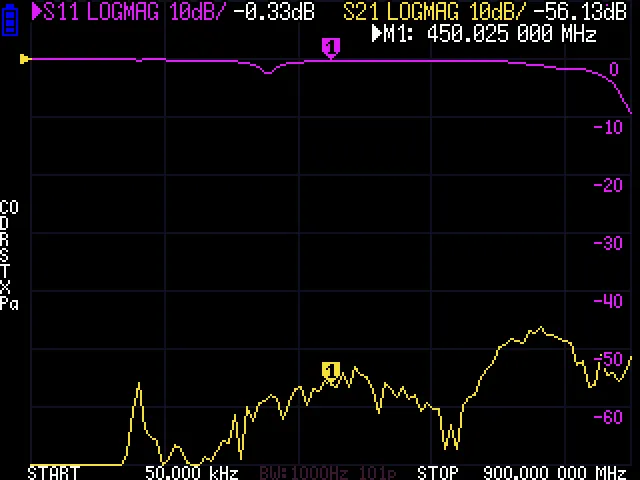
Enable S21 display
- Tap screen → DISPLAY → FORMAT S21 (THRU) → LOGMAG
- This shows transmission through the filter in dB
-
Place markers at the passband edges
- Enable MARKER 1 and place it in the passband center
- Enable MARKER 2 and MARKER 3 at the -3 dB rolloff points
-
Read the results
- Passband loss (how much signal you lose in the passband)
- Bandwidth (frequency range between -3 dB points)
- Stopband rejection (how well it blocks unwanted frequencies)
Save Your Data
Section titled “Save Your Data”If you have a microSD card (FAT16/FAT32 formatted):
- Insert the SD card into the slot on the device
- Tap screen → CONFIG → SD CARD
- Select SCREENSHOT to save the current display as a BMP image
- Select SAVE S1P to export S11 data as a Touchstone file
- Select SAVE S2P to export both S11 and S21 data
You can also transfer data to a PC over USB. See USB Connection for setup instructions.
Connect to a Computer (Optional)
Section titled “Connect to a Computer (Optional)”For larger screens, data logging, and advanced analysis:
- Connect USB — the NanoVNA-H appears as a virtual COM port (no special drivers needed on modern systems)
- Install software — NanoVNA Saver is a popular cross-platform choice
- Select the COM port in the software and connect
Quick Reference: Common Tasks
Section titled “Quick Reference: Common Tasks”| Task | Menu Path |
|---|---|
| Change frequency range | STIMULUS → START / STOP |
| Switch trace format | DISPLAY → FORMAT S11 or FORMAT S21 |
| Add a marker | MARKER → MARKER 1 |
| Find minimum SWR | MARKER → SEARCH → MIN |
| Calibrate | CALIBRATE → CALIBRATE → OPEN / SHORT / LOAD / DONE |
| Save calibration | CALIBRATE → SAVE → slot number |
| Recall calibration | RECALL → slot number |
| Take a screenshot | CONFIG → SD CARD → SCREENSHOT |
| Flip display | CONFIG → EXPERT SETTINGS → FLIP DISPLAY |
| Adjust trace scale | DISPLAY → SCALE → SCALE/DIV |
Troubleshooting
Section titled “Troubleshooting”Display is blank or garbled
Section titled “Display is blank or garbled”- Ensure the USB cable has data lines (not charge-only)
- Try pressing the jog wheel to wake the device
- If previously flipped, hold the jog wheel during power-on to reset
Calibration looks wrong
Section titled “Calibration looks wrong”- Make sure you calibrated at the same frequency range you are measuring
- Check that calibration standards are firmly connected (no wobble)
- Recalibrate if you changed cables after calibrating
Traces are noisy
Section titled “Traces are noisy”- Reduce IF bandwidth for cleaner measurements: STIMULUS → BANDWIDTH (lower = cleaner but slower)
- Ensure connectors are clean and tight
- Move away from strong RF sources that might interfere
Touch screen does not respond
Section titled “Touch screen does not respond”- Tap firmly — resistive screens need pressure, not just proximity
- Run touch calibration: connect via USB, send
touchcalcommand - See Touch Calibration