LC Matching Tool
The L/C Match function calculates component values for L-network matching circuits. Given the measured impedance at the marker position, it computes up to 4 matching solutions.
Enable L/C Match Mode
Section titled “Enable L/C Match Mode”- Tap the screen to open the menu
- Navigate to
DISPLAY > MEASURE - Tap
L/C MATCH - Position a marker at the frequency where you want to match
Understanding the Display
Section titled “Understanding the Display”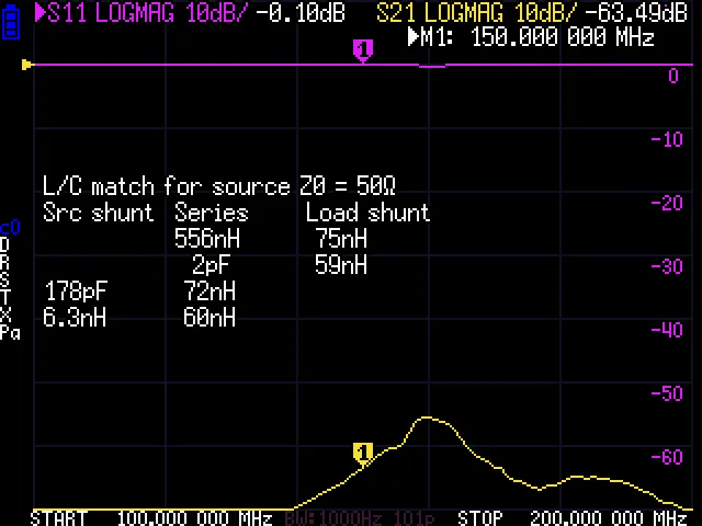
When L/C Match is active, the screen shows:
L/C match for source Z0 = 50 ohmsSrc shunt Series Load shunt --- 10.5 nH --- 47 pF 10.5 nH --- --- 8.2 nH 68 pF 47 pF 8.2 nH 68 pFEach row is a valid matching solution:
- Src shunt: Component in parallel with the source (50 ohm side)
- Series: Component in series between source and load
- Load shunt: Component in parallel with the load
Matching Solutions
Section titled “Matching Solutions”The L-network calculator provides different solutions depending on the load impedance:
High Impedance Loads (R > Z0)
Section titled “High Impedance Loads (R > Z0)”Two solutions using shunt capacitor/inductor at the load:
Source --- Series L/C --- Load | Shunt L/CLow Impedance Loads (R < Z0)
Section titled “Low Impedance Loads (R < Z0)”Two solutions using shunt capacitor/inductor at the source:
Source --- Series L/C --- Load |Shunt L/CNear 50 Ohms
Section titled “Near 50 Ohms”If the load is close to 50 ohms (SWR < 1.1), only a series reactance is needed to cancel the reactive component.
Reading Component Values
Section titled “Reading Component Values”The display shows:
- Positive values = Inductors (H, nH, uH)
- Negative values = Capacitors (F, pF, nF)
Example readings:
10.5 nH= 10.5 nanohenry inductor47 pF= 47 picofarad capacitor---= No component needed
Shell Commands
Section titled “Shell Commands”# Enable L/C match modemeasure lc
# Disable measurement modesmeasure nonePractical Example
Section titled “Practical Example”Matching a 25 + j30 ohm antenna to 50 ohms:
- Connect antenna to CH0
- Set sweep to cover the operating frequency
- Enable a marker at the desired frequency
- Go to
DISPLAY > MEASURE > L/C MATCH - Read the matching solutions
- Choose the solution that uses available component values
Choosing a Solution
Section titled “Choosing a Solution”When multiple solutions are presented, consider:
| Factor | Consideration |
|---|---|
| Component values | Choose values you have available |
| Bandwidth | Shunt at load gives wider bandwidth for high-Z loads |
| DC path | Series inductor allows DC pass-through |
| Harmonic suppression | Choose topology that attenuates harmonics |
| Physical size | Higher inductance = larger inductor |
Limitations
Section titled “Limitations”- Calculations assume ideal components (no losses, no parasitics)
- Valid only at the exact marker frequency
- Component values may need adjustment for real-world implementation
- Does not account for component Q factor
Building the Match
Section titled “Building the Match”Once you have the calculated values:
- Note the required component values
- Select standard component values close to calculated
- Build the L-network on a test board
- Measure the matched impedance with NanoVNA
- Adjust component values as needed for best match
Disable L/C Match
Section titled “Disable L/C Match”- Go to
DISPLAY > MEASURE - Tap
NONEto disable the measurement overlay