Trace Types
The NanoVNA-H firmware supports 30 distinct trace types, each providing a different view of the measured S-parameters. Trace types are organized by applicable channel (S11 reflection or S21 transmission).
Overview
Section titled “Overview”Each trace type has associated metadata controlling its display:
- Name: Short identifier shown on screen
- Unit: Measurement unit symbol
- Default Reference Position: Y-axis grid position for the reference level (0-based, NGRIDY=8)
- Default Scale: Units per vertical division
S11 (Reflection) Trace Types
Section titled “S11 (Reflection) Trace Types”These trace types display measurements from the CH0 (S11) channel, showing reflection characteristics of the DUT.
| Type | Name | Unit | Ref Position | Scale/Div | Description |
|---|---|---|---|---|---|
TRC_LOGMAG | LOGMAG | dB | 7 (top) | 10 dB | Logarithmic magnitude of reflection coefficient |
TRC_PHASE | PHASE | deg | 4 (center) | 90 deg | Phase angle of reflection coefficient |
TRC_DELAY | DELAY | s | 4 (center) | 1 ns | Group delay |
TRC_SMITH | SMITH | - | 0 | 1.0 | Smith chart (normalized impedance) |
TRC_POLAR | POLAR | - | 0 | 1.0 | Polar plot of reflection coefficient |
TRC_LINEAR | LINEAR | - | 0 | 0.125 | Linear magnitude of reflection coefficient |
TRC_SWR | SWR | - | 0 | 0.25 | Standing Wave Ratio |
TRC_REAL | REAL | - | 4 (center) | 0.25 | Real part of reflection coefficient |
TRC_IMAG | IMAG | - | 4 (center) | 0.25 | Imaginary part of reflection coefficient |
TRC_R | R | ohm | 0 | 100 ohm | Resistance (real part of impedance) |
TRC_X | X | ohm | 4 (center) | 100 ohm | Reactance (imaginary part of impedance) |
TRC_Z | |Z| | ohm | 0 | 50 ohm | Impedance magnitude |
TRC_ZPHASE | Z phase | deg | 4 (center) | 90 deg | Impedance phase angle |
TRC_G | G | S | 0 | 10 mS | Conductance |
TRC_B | B | S | 4 (center) | 10 mS | Susceptance |
TRC_Y | |Y| | S | 0 | 20 mS | Admittance magnitude |
TRC_Rp | Rp | ohm | 0 | 100 ohm | Parallel resistance |
TRC_Xp | Xp | ohm | 4 (center) | 100 ohm | Parallel reactance |
TRC_sC | sC | F | 4 (center) | 10 nF | Series capacitance |
TRC_sL | sL | H | 4 (center) | 10 nH | Series inductance |
TRC_pC | pC | F | 4 (center) | 10 nF | Parallel capacitance |
TRC_pL | pL | H | 4 (center) | 10 nH | Parallel inductance |
TRC_Q | Q | - | 0 | 10 | Quality factor |
S21 (Transmission) Trace Types
Section titled “S21 (Transmission) Trace Types”These trace types work with both S11 and S21 channels, but some are specifically designed for S21 transmission measurements.
Universal Types (S11 and S21)
Section titled “Universal Types (S11 and S21)”| Type | Name | Unit | Ref Position | Scale/Div | Description |
|---|---|---|---|---|---|
TRC_LOGMAG | LOGMAG | dB | 7 (top) | 10 dB | Logarithmic magnitude |
TRC_PHASE | PHASE | deg | 4 (center) | 90 deg | Phase angle |
TRC_DELAY | DELAY | s | 4 (center) | 1 ns | Group delay |
TRC_SMITH | SMITH | - | 0 | 1.0 | Smith chart display |
TRC_POLAR | POLAR | - | 0 | 1.0 | Polar plot |
TRC_LINEAR | LINEAR | - | 0 | 0.125 | Linear magnitude |
TRC_REAL | REAL | - | 4 (center) | 0.25 | Real part |
TRC_IMAG | IMAG | - | 4 (center) | 0.25 | Imaginary part |
S21-Specific Types
Section titled “S21-Specific Types”| Type | Name | Unit | Ref Position | Scale/Div | Description |
|---|---|---|---|---|---|
TRC_Rser | Rser | ohm | 4 (center) | 100 ohm | Series resistance (from S21) |
TRC_Xser | Xser | ohm | 4 (center) | 100 ohm | Series reactance (from S21) |
TRC_Zser | |Zser| | ohm | 4 (center) | 100 ohm | Series impedance magnitude |
TRC_Rsh | Rsh | ohm | 4 (center) | 100 ohm | Shunt resistance (from S21) |
TRC_Xsh | Xsh | ohm | 4 (center) | 100 ohm | Shunt reactance (from S21) |
TRC_Zsh | |Zsh| | ohm | 4 (center) | 100 ohm | Shunt impedance magnitude |
TRC_Qs21 | Q | - | 0 | 10 | Quality factor (from S21) |
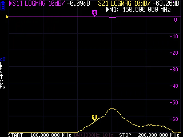
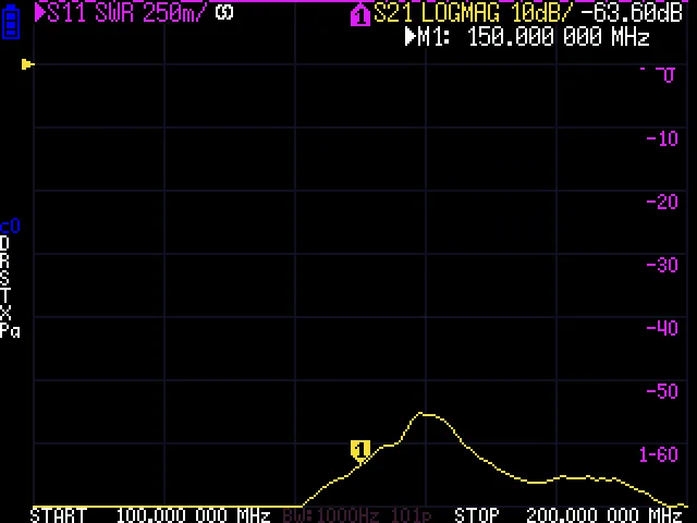
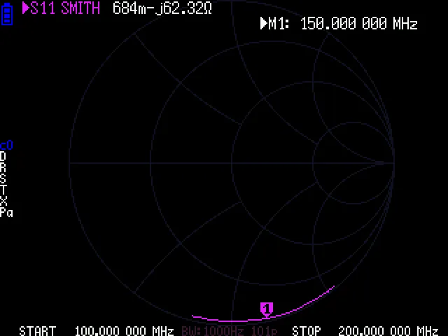
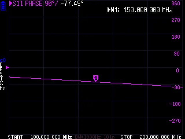
Common Trace Types — Visual Reference
Section titled “Common Trace Types — Visual Reference”The four most-used trace formats. Each screenshot is captured directly from the NanoVNA-H LCD.
LOGMAG — Return loss or insertion loss in dB:
SWR — Standing wave ratio for antenna tuning:
Smith Chart — Complex impedance on a normalized grid:
Phase — Reflection or transmission phase in degrees:
Trace Type Categories
Section titled “Trace Type Categories”Rectangular Grid Types
Section titled “Rectangular Grid Types”Most trace types display on a rectangular grid with frequency on the X-axis:
LOGMAG, PHASE, DELAY, LINEAR, SWR, REAL, IMAG,R, X, Z, ZPHASE, G, B, Y, Rp, Xp,sC, sL, pC, pL, Q,Rser, Xser, Zser, Rsh, Xsh, Zsh, Qs21Circular/Polar Grid Types
Section titled “Circular/Polar Grid Types”These types display on a circular grid:
- SMITH: Normalized impedance on Smith chart (real axis 0-infinity, imaginary axis -j to +j)
- POLAR: Complex reflection coefficient (magnitude 0-1, angle 0-360 deg)
Nano-Scale Types
Section titled “Nano-Scale Types”These types use nano/pico unit scaling for input values:
DELAY (nanoseconds), sC, sL, pC, pL (nanofarads/nanohenries)Display Format Strings
Section titled “Display Format Strings”Each trace type has associated format strings for marker readout:
| Type | Value Format | Delta Format | Example Output |
|---|---|---|---|
| LOGMAG | %.2f dB | delta %.3f dB | -3.25 dB |
| PHASE | %.2f deg | delta %.2f deg | 45.00 deg |
| DELAY | %.4F s | %.4F s | 1.234 ns |
| SWR | %.3f | delta %.3f | 1.500 |
| R, X, Z | %.3F ohm | delta %.3F ohm | 50.0 ohm |
| G, B, Y | %.3F S | delta %.3F S | 20.0 mS |
| sC, pC | %.4F F | delta %.4F F | 10.00 pF |
| sL, pL | %.4F H | delta %.4F H | 100.0 nH |
The %F format applies automatic SI prefix scaling (k, M, G, m, u, n, p).
Trace Configuration
Section titled “Trace Configuration”Each trace has the following configuration parameters stored in trace_t:
typedef struct trace { uint8_t enabled; // 0=disabled, 1=enabled uint8_t type; // TRC_LOGMAG, TRC_PHASE, etc. uint8_t channel; // 0=S11, 1=S21 uint8_t smith_format; // Smith chart marker format (MS_LIN, MS_LOG, etc.) float scale; // Units per division float refpos; // Reference position (0-NGRIDY)} trace_t;Maximum trace count is 4 active traces (TRACES_MAX = 4), plus 1 stored trace (STORED_TRACES = 1).
Source Code Reference
Section titled “Source Code Reference”Trace type definitions are located in:
- Enum definition:
nanovna.hlines 837-847 - Trace info table:
plot.clines 564-596 (trace_info_list[]) - Trace structure:
nanovna.hlines 989-996